Processing e Conversor Digital Analógico DAC MCP4725
O que você faz quando precisa de uma saída analógica no Arduino? Geralmente recorre à saída PWM, correto? Hoje vou apresentar uma outra opção para você que precisa de uma saída analógica real no Arduino: o Conversor Digital Analógico DAC MCP4725.
O Conversor Digital Analógico DAC MCP4725 trabalha com interface I2C e tensões de 3,3 ou 5V, com resolução de até 12 bits. Pode ser utilizado em circuitos de áudio e projetos que exijam uma variação de tensão analógica.
E como funciona ? Envie um valor digital para o módulo (de 0 a 4095, no caso da resolução de 12 bits), e o módulo vai gerar uma tensão proporcional no pino Vout. A tensão de saída está diretamente relacionada à tensão de alimentação do módulo: se você alimentar com 3.3V, o valor de saída estará entre 0 e 3.3V, se você alimentar com 5V, a saída estará entre 0 e 5V.
Pinagem e características do Conversor Digital Analógico MCP4725
O Conversor Digital Analógico MCP4725 é bem simples de usar, e vamos observar isso já na pinagem do módulo, que além dos pinos de alimentação possui os pinos para interface I2C e o Vout, que é o único pino de saída, onde teremos o sinal analógico:
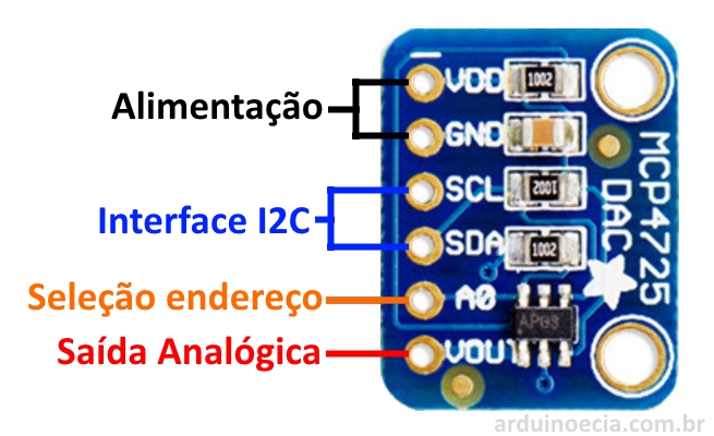
O pino A0 serve para alterar o endereço I2C do módulo. Por padrão, o endereço do MCP4725 é 0x62. Aplique tensão (até 5V) no pino A0, e o endereço passa a ser 0x63. Isso significa que podemos ter 2 módulos MCP4725 ao mesmo tempo no barramento I2C.
Além disso, esse módulo também tem uma pequena EEPROM, que armazena o valor da tensão de saída que foi programada, assim você não precisa, cada vez que executar o programa, dizer qual é a tensão de saída.
Conexão e teste do módulo MCP4725
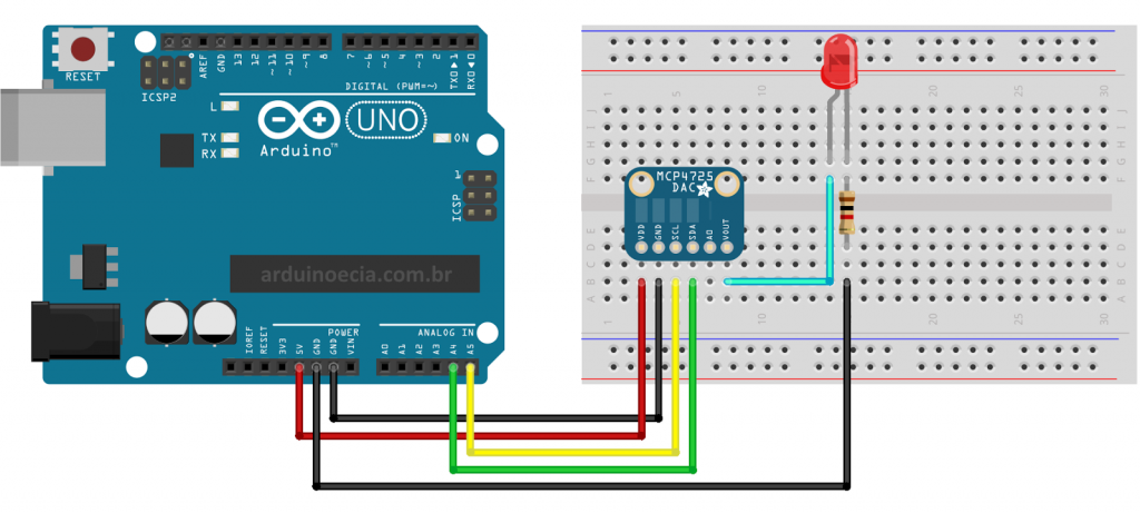
Você pode testar o MCP4725 conectando um led na saída do módulo e carregando um programa que gera uma onda senoidal nessa saída. Para isso, monte o seguinte circuito:
Agora, vá até este link e baixe a biblioteca Adafruit_MCP4725. Descompacte a biblioteca e coloque-a dentro da pasta LIBRARIES da IDE do Arduino.
Carregue o programa abaixo, que é o programa de exemplo Sinewave da biblioteca da Adafruit, e nele fiz algumas alterações nele para que não ficasse muito extenso aqui no post, utilizando apenas a resolução de 9 bits:
//Programa: Onda Senoidal MCP4725
//Alteracoes e adaptacoes: Arduino e Cia
//
//Baseado no programa de exemplo Sineware - Adafruit

#include <Wire.h>
#include <Adafruit_MCP4725.h>

Adafruit_MCP4725 dac;

//Define a resolucao
#define DAC_RESOLUTION    (9)

const PROGMEM uint16_t DACLookup_FullSine_9Bit[512] =
{
  2048, 2073, 2098, 2123, 2148, 2174, 2199, 2224,
  2249, 2274, 2299, 2324, 2349, 2373, 2398, 2423,
  2448, 2472, 2497, 2521, 2546, 2570, 2594, 2618,
  2643, 2667, 2690, 2714, 2738, 2762, 2785, 2808,
  2832, 2855, 2878, 2901, 2924, 2946, 2969, 2991,
  3013, 3036, 3057, 3079, 3101, 3122, 3144, 3165,
  3186, 3207, 3227, 3248, 3268, 3288, 3308, 3328,
  3347, 3367, 3386, 3405, 3423, 3442, 3460, 3478,
  3496, 3514, 3531, 3548, 3565, 3582, 3599, 3615,
  3631, 3647, 3663, 3678, 3693, 3708, 3722, 3737,
  3751, 3765, 3778, 3792, 3805, 3817, 3830, 3842,
  3854, 3866, 3877, 3888, 3899, 3910, 3920, 3930,
  3940, 3950, 3959, 3968, 3976, 3985, 3993, 4000,
  4008, 4015, 4022, 4028, 4035, 4041, 4046, 4052,
  4057, 4061, 4066, 4070, 4074, 4077, 4081, 4084,
  4086, 4088, 4090, 4092, 4094, 4095, 4095, 4095,
  4095, 4095, 4095, 4095, 4094, 4092, 4090, 4088,
  4086, 4084, 4081, 4077, 4074, 4070, 4066, 4061,
  4057, 4052, 4046, 4041, 4035, 4028, 4022, 4015,
  4008, 4000, 3993, 3985, 3976, 3968, 3959, 3950,
  3940, 3930, 3920, 3910, 3899, 3888, 3877, 3866,
  3854, 3842, 3830, 3817, 3805, 3792, 3778, 3765,
  3751, 3737, 3722, 3708, 3693, 3678, 3663, 3647,
  3631, 3615, 3599, 3582, 3565, 3548, 3531, 3514,
  3496, 3478, 3460, 3442, 3423, 3405, 3386, 3367,
  3347, 3328, 3308, 3288, 3268, 3248, 3227, 3207,
  3186, 3165, 3144, 3122, 3101, 3079, 3057, 3036,
  3013, 2991, 2969, 2946, 2924, 2901, 2878, 2855,
  2832, 2808, 2785, 2762, 2738, 2714, 2690, 2667,
  2643, 2618, 2594, 2570, 2546, 2521, 2497, 2472,
  2448, 2423, 2398, 2373, 2349, 2324, 2299, 2274,
  2249, 2224, 2199, 2174, 2148, 2123, 2098, 2073,
  2048, 2023, 1998, 1973, 1948, 1922, 1897, 1872,
  1847, 1822, 1797, 1772, 1747, 1723, 1698, 1673,
  1648, 1624, 1599, 1575, 1550, 1526, 1502, 1478,
  1453, 1429, 1406, 1382, 1358, 1334, 1311, 1288,
  1264, 1241, 1218, 1195, 1172, 1150, 1127, 1105,
  1083, 1060, 1039, 1017,  995,  974,  952,  931,
  910,  889,  869,  848,  828,  808,  788,  768,
  749,  729,  710,  691,  673,  654,  636,  618,
  600,  582,  565,  548,  531,  514,  497,  481,
  465,  449,  433,  418,  403,  388,  374,  359,
  345,  331,  318,  304,  291,  279,  266,  254,
  242,  230,  219,  208,  197,  186,  176,  166,
  156,  146,  137,  128,  120,  111,  103,   96,
  88,   81,   74,   68,   61,   55,   50,   44,
  39,   35,   30,   26,   22,   19,   15,   12,
  10,    8,    6,    4,    2,    1,    1,    0,
  0,    0,    1,    1,    2,    4,    6,    8,
  10,   12,   15,   19,   22,   26,   30,   35,
  39,   44,   50,   55,   61,   68,   74,   81,
  88,   96,  103,  111,  120,  128,  137,  146,
  156,  166,  176,  186,  197,  208,  219,  230,
  242,  254,  266,  279,  291,  304,  318,  331,
  345,  359,  374,  388,  403,  418,  433,  449,
  465,  481,  497,  514,  531,  548,  565,  582,
  600,  618,  636,  654,  673,  691,  710,  729,
  749,  768,  788,  808,  828,  848,  869,  889,
  910,  931,  952,  974,  995, 1017, 1039, 1060,
  1083, 1105, 1127, 1150, 1172, 1195, 1218, 1241,
  1264, 1288, 1311, 1334, 1358, 1382, 1406, 1429,
  1453, 1478, 1502, 1526, 1550, 1575, 1599, 1624,
  1648, 1673, 1698, 1723, 1747, 1772, 1797, 1822,
  1847, 1872, 1897, 1922, 1948, 1973, 1998, 2023
};

void setup(void)
{
  Serial.begin(9600);
  Serial.println("Ola !");
  //Inicializa o MCP4725 no endereco 0x62
  dac.begin(0x62);
  Serial.println("Gerando onda senoidal");
}

void loop()
{
  uint16_t i;
  for (i = 0; i < 512; i++)
  {
    dac.setVoltage(pgm_read_word(&(DACLookup_FullSine_9Bit[i])), false);
    delay(7);
  }
}
Após carregar o programa, o led vai acender e apagar em intervalos regulares, variando a intensidade do brilho.
Utilizando o Processing como Osciloscópio
O exemplo do led serve bem para testar o módulo, mas o ideal seria verificar, em um osciloscópio, o formato de onda na saída do MCP4725. Eu encontrei um programa muito interessante para o Processing, que faz com que ele simule um osciloscópio, lendo os valores da porta analógica A0 e convertendo isso para o formato de gráfico. Nesse caso, vamos interligar dois Arduinos:
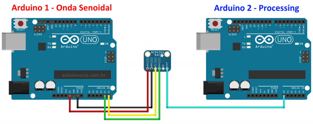
No Arduino 1 vamos carregar o mesmo programa que utilizamos no exemplo do led. Já no Arduino 2, carregue o programa abaixo:
// Oscilloscope
// Input defined by ANALOG_IN
// SIG_OUT true puts a 2kHz wave on DIGITAL_OUT for testing.

#define ANALOG_IN 0
#define DIGITAL_OUT 13
bool SIG_OUT = false;

void setup() {
  Serial.begin(9600);
  //Serial.begin(115200);

  // Generate a signal to examine (testing)
  if(SIG_OUT){
    pinMode(DIGITAL_OUT, OUTPUT);

    // initialize timer1
    noInterrupts();           // disable all interrupts
    TCCR1A = 0;
    TCCR1B = 0;
    TCNT1  = 0;

    OCR1A = 31250;            // compare match register 16MHz/256/2Hz
    TCCR1B |= (1 << WGM12);   // CTC mode
    TCCR1B |= (1 << CS12);    // 256 prescaler
    TIMSK1 |= (1 << OCIE1A);  // enable timer compare interrupt
    interrupts();             // enable all interrupts
  }
}

// Interrupt based
ISR(TIMER1_COMPA_vect){
  digitalWrite(DIGITAL_OUT, digitalRead(DIGITAL_OUT) ^ 1);   // Toggle
}

void loop() {
  int val = analogRead(ANALOG_IN);
  Serial.write( 0xff );
  Serial.write( (val >> 8) & 0xff );
  Serial.write( val & 0xff );
}
Esse programa do Arduino é o responsável por ler os dados da porta A0, onde está ligado o Vout do MCP4725, e enviar esses dados para o Processing.
(Para informações sobre a instalação e utilização do Processing com Arduino, veja o post Processing: mostre as informações do Arduino no seu computador).
Carregue agora o seguinte programa no Processing. (Créditos para John Porter e Sofian Audry, que criaram e desenvolveram esse código). A única alteração que eu fiz foi acrescentar a linha azul que mostra o nível de tensão de 3.3V. Na linha 78 você configura a porta utilizada pelo seu Arduino:
/*
* Oscilloscope
 * Gives a visual rendering of analog pin in realtime.
 *
 * ---------------- IMPROVEMENTS ------------------
 * Updates by John Porter, 2/7/2014
 * Added ability to move waveform left or right.
 * Added gridlines (bounds and minor).
 * Added ability to pause/resume.
 * Added ability to measure time.
 * General usability improvements.
 *
 * --------------- ORIGINAL PROJECT ---------------
 * This project is part of Accrochages
 * See http://accrochages.drone.ws
 * (c) 2008 Sofian Audry ([email protected])
 * ------------------------------------------------
 *
 * This program is free software: you can redistribute it and/or modify
 * it under the terms of the GNU General Public License as published by
 * the Free Software Foundation, either version 3 of the License, or
 * (at your option) any later version.
 *
 * This program is distributed in the hope that it will be useful,
 * but WITHOUT ANY WARRANTY; without even the implied warranty of
 * MERCHANTABILITY or FITNESS FOR A PARTICULAR PURPOSE. See the
 * GNU General Public License for more details.
 *
 * You should have received a copy of the GNU General Public License
 * along with this program. If not, see <http://www.gnu.org/licenses/>.
 */

// * ------------------ HOT KEYS ------------------
final char T_UP       = 'w'; // Translate waveform up
final char T_DOWN     = 's'; //                    down
final char T_LEFT     = 'a'; //                    left
final char T_RIGHT    = 'd'; //                    right
final char Z_IN       = 'c'; // Horizontal zoom in
final char Z_OUT      = 'z'; //                 out
final char S_IN       = 'e'; // Vertical scale in
final char S_OUT      = 'q'; //                out
final char MGL_UP     = 'r'; // Minor grid lines increase
final char MGL_DOWN   = 'f'; //                  decrease
final char TOG_PAUSE  = 'p'; // Toggle pause (unpause resets waveform)
final char RESET_AXIS = ' '; // Reset axis settings
final char MEAS_TIME  = 'x'; // Adds and/or highlights vertical bars (time measurement)
final char BAR_LEFT   = ','; // Move highlighted vertical bar left (can also mouse click)
final char BAR_RIGHT  = '.'; //                               right
// * ----------------------------------------------

// * --------------- STARTING STATE ---------------
float zoom    = 1.0;
float scale   = 0.5;
int centerV   = 0;
int centerH   = 0;
int gridLines = 0;
int com_port  = 1;   // Index number in Serial.list
// * ----------------------------------------------

// Global vars
import processing.serial.*;
Serial port;                    // Create object from Serial class
int val;                        // Data received from the serial port
long valTime;                   // Time data was received
int[] values;
long[] times;
float voltage;
float measTime = 0;
int   timeMode = 0;
int[] timeBars = {0, 0};
PFont f;
boolean pause;

// Setup
void setup() {
  size(580, 400);
  printArray(Serial.list());
  port = new Serial(this, Serial.list()[0], 9600);    // Com port specified here
  values = new int[width];
  times = new long[width];
  timeBars[0] = width/3;
  timeBars[1] = 2*width/3;
  pause = false;
  smooth();
  f = createFont("Arial", 16, true);
}

// Read value from serial stream
int getValue() {
  int value = -1;
  while (port.available () >= 3) {
    if (port.read() == 0xff) {
      value = (port.read() << 8) | (port.read());
    }
  }
  return value;
}

// Get a y-value for the datapoint, varies based on axis settings
int getY(int val) {
  return (int)(height/2 -(val-512+centerV)*scale / 1023.0f * (height - 1));
}

// Push the values in the data array
void pushValue(int value) {
  for (int i=0; i<width-1; i++)
    values[i] = values[i+1];
  values[width-1] = value;
}

// Push the timestamps in the time array
void pushTime(long time) {
  for (int i=0; i<width-1; i++)
    times[i] = times[i+1];
  times[width-1] = time;
}

// Draw waveform
void drawLines() {
  int x0 = 0, x1 = 0, y0 = 0, y1 = 0;
  stroke(255,255,0);
  for (int i=0; i<width; i++) {
    x1 = round(width - ((width-i) * zoom) + centerH);
    y1 = getY(values[i]);
    if(i > 1)
      line(x0, y0, x1, y1);
    x0 = x1;
    y0 = y1;
  }
}

// Draw gridlines (bounds, minor)
void drawGrid() {
  // Get scaled values for bounds
  int pFive = getY(1023);
  int pTres = getY(680);
  int zero  = getY(0);

  // Draw voltage bounds
  stroke(255, 0, 0);
  line(0, pFive-1, width, pFive-1);
  line(0, zero+1, width, zero+1);
  stroke(0, 38, 255);
  line(0, pTres-1, width, pTres-1);


  // Add voltage bound text
  textFont(f, 10);
  fill(255, 0, 0);
  text("+5V", 5, pFive+12);
  text(" 0V", 5, zero-4);
  fill(0, 38, 255);
  text("+3.3V", 5, pTres+12);


  // Draw minor grid lines
  int gridVal = 0;
  stroke(75, 75, 75);
  for (int i = 0; i < gridLines; i++) {
    gridVal = getY(round((i+1.0)*(1023.0 / (gridLines+1.0))));
    line(0, gridVal, width, gridVal);
  }

  // Add minor grid line text
  if (gridLines > 0) {
    textFont(f, 16);
    fill(204, 102, 0);
    float scaleVal = truncate(5.0f / (gridLines+1), 3);
    text("Grid: " + scaleVal + "V", 1170, height-12);
  }

  // Print difference between vertical 'time' bars
  if (timeMode > 0) {
    textFont(f, 16);
    fill(204, 102, 0);

    int idx0 = round(width + (timeBars[0] - width - centerH)/zoom);
    int idx1 = round(width + (timeBars[1] - width - centerH)/zoom);

    // Ensure time bars are over a recorded portion of the waveform
    if(idx1 < 0 || idx0 < 0 || idx1 > (width-1) || idx0 > (width-1) || times[idx1] == 0 || times[idx0] == 0)
      text("Time: N/A", 30, height-12);
    else{
      float timeDiff = truncate((times[idx1] - times[idx0])/2000000.0,2);
      text("Time: " + timeDiff + "ms", 30, height-12);
    }
  }
}

// Draw vertical 'time bars' (seperate from above for better layering)
void drawVertLines(){
  stroke(75, 75, 75);
  if (timeMode == 1) {
    line(timeBars[1], 0, timeBars[1], height);
    stroke(100, 100, 255);
    line(timeBars[0], 0, timeBars[0], height);
  }
  else if (timeMode == 2) {
    line(timeBars[0], 0, timeBars[0], height);
    stroke(100, 255, 100);
    line(timeBars[1], 0, timeBars[1], height);
  }
}

// Truncate a floating point number
float truncate(float x, int digits) {
  float temp = pow(10.0, digits);
  return round( x * temp ) / temp;
}

// When a key is pressed down or held...
void keyPressed() {
  switch (key) {
  case T_UP: centerV += 10/scale; break;                     // Move waveform up
  case T_DOWN: centerV -= 10/scale; break;                   // Move waveform down
  case T_RIGHT: centerH += 10/scale; break;                  // Move waveform right
  case T_LEFT: centerH -= 10/scale; break;                   // Move waveform left
  case MGL_UP:                                               // Increase minor grid lines
    if (gridLines < 49)
      gridLines += 1;
    break;
  case MGL_DOWN:                                             // Decrease minor grid lines
    if (gridLines > 0)
      gridLines -= 1;
    break;
  case BAR_LEFT:                                             // Move the time bar left (also mouse click)
    if (timeMode == 1 && timeBars[0] > 0)
      timeBars[0] -= 1;
    else if (timeMode == 2 && timeBars[1] > 0)
      timeBars[1] -= 1;
    break;
  case BAR_RIGHT:                                            // Move the time bar right (also mouse click)
    if (timeMode == 1 && timeBars[0] < width-1)
      timeBars[0] += 1;
    else if (timeMode == 2 && timeBars[1] < width-1)
      timeBars[1] += 1;
    break;
  }
}

// When a key is released...
void keyReleased() {
  println(key+": "+(int)key);
  switch (key) {
  case Z_IN:                                                 // Zoom horizontal
    zoom *= 2.0f;
    if ( (int) (width / zoom) <= 1 )
      zoom /= 2.0f;
    break;
  case Z_OUT:                                                // Zoom horizontal
    zoom /= 2.0f;
    if (zoom < 1.0f)
      zoom *= 2.0f;
    break;
  case S_IN: scale*=2; break;                                // Scale vertical
  case S_OUT: scale /= 2; break;                             // Scale vertical
  case RESET_AXIS:                                           // Reset all scaling
    centerV = 0; centerH = 0;
    scale = 0.5; zoom  = 1; gridLines = 0;
    break;
  case MEAS_TIME: timeMode = (timeMode + 1) % 3; break;      // Change the vertical bars (off, left bar, right bar)
  case TOG_PAUSE:                                            // Toggle waveform pausing
    if (pause) {
      centerH = 0;
      for (int i=0; i<width; i++){
        values[i] = 0;                                       // Clear data on resume
        times[i] = 0;
      }
    }
    pause = !pause;
  }
}

// Use mouse clicks to quickly move vertical bars (if highlighted)
void mousePressed() {
  if(timeMode == 1)
    timeBars[0] = mouseX;
  else if(timeMode == 2)
    timeBars[1] = mouseX;
}

// Primary drawing function
void draw()
{
  background(0);
  drawGrid();
  // Get current voltage, time of reading
  val = getValue();
  valTime = System.nanoTime();

  // If not paused
  if (!pause && val != -1) {
    // Push value/time onto array
    pushValue(val);
    pushTime(valTime);

    // Print current voltage reading
    textFont(f, 16);
    fill(204, 102, 0);
    voltage = truncate(5.0*val / 1023, 1);
    text("Voltage: " + voltage + "V", 470, 30);
  }
  drawLines();
  drawVertLines();
}
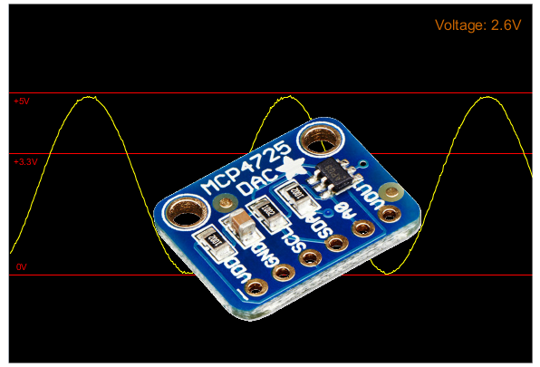
Execute o programa e você terá como resultado a tela abaixo, com a onda senoidal gerada na saída do Conversor Digital Analógico MCP4725:
Carregando o programa de exemplo trianglewave da biblioteca da Adafruit, e alimentando o módulo MCP4725 com 3.3V, temos o seguinte resultado:
Explore outras funções para esse programa, como por exemplo análise de ondas quadradas, sinal de temporizadores, verificar nível de sinal de módulos, etc.
Gostou? Confira outros posts usando Processing aqui mesmo no Arduino e Cia!

Olá, muito bom o post. Poderia me dizer como posso alterar a frequencia da senoide? E qual a faixa de frequencia? Obrigado pela atenção.
Altere o valor do delay no final do codigo.
Ola pessoal, gostaria de saber como faço para realizar a leitura de 40 tensões simultâneas com arduino, alguém pode me ajudar?
Obrigado!
Use 3 módulos 74HC4067, a saída de cada um em uma entrada analógica do Arduino. Cada um pode selecionar 16 sinais diferentes para cada entrada analógica do arduino. As entradas S0, S1, S2 e S3 dos módulos, ligue a 4 saídas digitais do Arduino. No programa, use "digitalWrite" para colocar nestas saídas o endereço da entrada que vai ser lida. Com 3 módulos serão 48 tensões diferentes a serem monitoradas.
Pessoal, alguém sabe onde posso encontrar esse MCP4725 mas navesão A1, ou seja, MCP4725A1. Estou precisando usar 3 MCP4725, mas os que tem a venda no filipeflop só tem a versão MCP4725A0, que só permite 2 placas na mesmo bus.